Change Management is the process of managing requests to change the software after it has been deployed into production. This article discusses the concepts associated with change management including the change control manager, the change management request and the change management process.
Change management is the methodology used to manage changes to software in production. There are several reasons why software changes after it has been released into production:
1. If a user uncovers a defect, not encountered during testing, a Request is submitted to fix the defect.
It may seem that if testing was performed on software defects should not be encountered. However, this thought is not true. When a test case is created, depending on the software functionality, variations of the test items are used to ensure the software behaves the way it is supposed to. For example, there may be a test case designed to test various scenarios associated with adding a customer order. For example, a requirement may state that “if, on Tuesday, a customer’s order is $100 or more the customer shall receive a $10 discount on the order.” This one requirement requires multiple test scenarios to ensure the system behaves as stated. For example, one test scenario may include creating an order, on Tuesday, that totals $99.99 to make sure a discount isn’t added to orders below $100. Another scenario may test adding an order on Monday to make sure the $10 discount isn't added to orders over $100.00. The tester will also need to create a test scenario to make sure the discount is added, to orders over $100.00, on Tuesday. The tester will even create scenarios that test adding orders over $100 for Thursday through Sunday to make sure discounts are only added on the correct day. This is necessary because there are various ways the requirements can be programmed. The programming logic used to create the procedure that calculates and applies the discount is what drives how the software will behave when tested using different scenarios. Therefore, it is possible for a tester to test the software and the user may still uncover a scenario that wasn’t covered during testing.
2. If a user submits a Request identifying required software functionality that is missing; a request to enhance the software is submitted.
Let’s say all of the requirements have been gathered. Everyone agrees that all of the requirements are listed. The stakeholder prioritizes the requirements. However, a requirement that was supposed to be implemented in the first release was overlooked. For example, the “delete order” functionality was omitted. A customer then calls the Help Desk and requests to delete an order; but the functionality was not included in the current release. Although there is an upcoming planned release; an immediate enhancement may need to be performed to support customer satisfaction.
3. A menu or button name or other text built into the software may be misspelled. A Request will also be submitted to request this change.
Typically, during the planning phase of the project, a plan is defined regarding how the software change will be managed. This information is usually outlined in the Configuration Management Plan, which is part of the Software Development Plan. Configuration Management and Change Management typically go hand-in-hand. This is because Configuration Management involves concepts used to assign a unique identifier to software builds and artifacts so all items related to a particular version of software may can be identified.
Change Management is implemented as part of the Help Desk Support services. Often help desk software (such as IBM's Remedy) is used along with Change Management software. The Help Desk software manages problem requests. However, the problems may not require change to software. This is why the two separate software systems are used. For example, a user may encounter problems using software because the user may not understand how to properly operate the software. The user may then call the Help Desk. The Help Desk Specialist can instruct the user on how to perform the task properly and the Help Desk ticket is closed. Change Management software, on the other hand, captures requests for change or CRs. A Help Desk associate may enter the CR. Or, depending on the organization, business analysts and end-users may enter CRs.
The CR is associated with statuses so it may move through a process. This approach ensures the appropriate notifications are sent to the applicable people to alert them about the CR and related activities. The most commonly used statuses are as follows: Submitted, Postponed, Opened, More Information, Rejected, Assigned, Resolved, Test Failed, Verified, Closed.
When a CR is entered it is assigned a "Submitted" status. After the Change Control Board (CCB) accesses the CR it moves to the Open, More Info, Postponed, Rejected, or Closed state. Following is a brief description of these statuses:
The Change Control Board (also referred to as the change control manager) is responsible for ensuring a cohesive Change Control process is used. The Change Control Board is made up of a group of people who represent users, developers, testers, project managers and executives. The job of the Change Control Board is to review the CR to ensure the request is appropriate and necessary. A Chair is also assigned to head the Change Control Board. The Chair is used to handle problems and enforce the Change Control Board's decisions.
The amount of work performed by the Change Control Board is usually driven by the size of the organization. For example, a large organization that has multiple applications may need to review information from the Software Architecture before making a decision. The Change Control Board will request a report that shows software capabilities for each software component. Each software components is associated with the name of the software so the Change Control Board can tell what software offers what capabilities:
If a request is made for software capability that already exists for the same software further clarification, regarding the request, is requested. In addition, the CCB may ask for an Impact Analysis Report. If this occurs a Tester is asked to create the test cases and test items. The test cases and test items are traced so the amount of work can be properly accessed by the CCB. The CCB takes costs, risks and other organizational objectives and concerns into consideration before making a decision. If the CCB agrees to the change it will also identify when the change should be made (i.e., now or a specific release).
Change management is the methodology used to manage changes to software in production. The Change Request (CR) is a form. An organization may use a paper CR or an online CR. IBM's Rational ClearQuest is the most commonly used Change Management software used to submit and manage change requests. The Change Control Board is also referred to as the change control manager. The change control manager is responsible for overseeing the overall Change Control process.
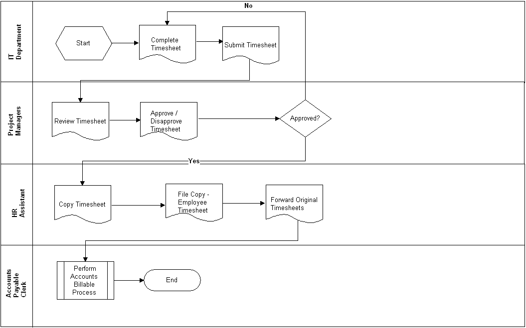
Each Change Request must move through the defined Change Control process. Depending on the organization the process may be as follows: The Submitter submits the Change Request. Next, the Change Control Board Reviews the request. If the change is approved the software developer makes the change; and, the technical writer and/or technical trainer updates related guides. Once the change is completed the tester tests the change. Lastly, once the change has successfully passed testing it is deployed into production as scheduled and the release notes are distributed to users.
What is Change Management?
Change management is the methodology used to manage changes to software in production. There are several reasons why software changes after it has been released into production:
1. If a user uncovers a defect, not encountered during testing, a Request is submitted to fix the defect.
It may seem that if testing was performed on software defects should not be encountered. However, this thought is not true. When a test case is created, depending on the software functionality, variations of the test items are used to ensure the software behaves the way it is supposed to. For example, there may be a test case designed to test various scenarios associated with adding a customer order. For example, a requirement may state that “if, on Tuesday, a customer’s order is $100 or more the customer shall receive a $10 discount on the order.” This one requirement requires multiple test scenarios to ensure the system behaves as stated. For example, one test scenario may include creating an order, on Tuesday, that totals $99.99 to make sure a discount isn’t added to orders below $100. Another scenario may test adding an order on Monday to make sure the $10 discount isn't added to orders over $100.00. The tester will also need to create a test scenario to make sure the discount is added, to orders over $100.00, on Tuesday. The tester will even create scenarios that test adding orders over $100 for Thursday through Sunday to make sure discounts are only added on the correct day. This is necessary because there are various ways the requirements can be programmed. The programming logic used to create the procedure that calculates and applies the discount is what drives how the software will behave when tested using different scenarios. Therefore, it is possible for a tester to test the software and the user may still uncover a scenario that wasn’t covered during testing.
2. If a user submits a Request identifying required software functionality that is missing; a request to enhance the software is submitted.
Let’s say all of the requirements have been gathered. Everyone agrees that all of the requirements are listed. The stakeholder prioritizes the requirements. However, a requirement that was supposed to be implemented in the first release was overlooked. For example, the “delete order” functionality was omitted. A customer then calls the Help Desk and requests to delete an order; but the functionality was not included in the current release. Although there is an upcoming planned release; an immediate enhancement may need to be performed to support customer satisfaction.
3. A menu or button name or other text built into the software may be misspelled. A Request will also be submitted to request this change.
The Change Request
The Change Request (CR) is a form. An organization may use a paper CR or an online CR. IBM's Rational ClearQuest is the most commonly used Change Management software. However, online CRs are more practical because the software can ensure the process is properly executed for each request. The CR provides information about the software product to be changed, the type of change requested (i.e., enhancement, defect, etc.), details about the change, the name of the person requesting the change, etc.
Typically, during the planning phase of the project, a plan is defined regarding how the software change will be managed. This information is usually outlined in the Configuration Management Plan, which is part of the Software Development Plan. Configuration Management and Change Management typically go hand-in-hand. This is because Configuration Management involves concepts used to assign a unique identifier to software builds and artifacts so all items related to a particular version of software may can be identified.
The Change Management Process
Change Management is implemented as part of the Help Desk Support services. Often help desk software (such as IBM's Remedy) is used along with Change Management software. The Help Desk software manages problem requests. However, the problems may not require change to software. This is why the two separate software systems are used. For example, a user may encounter problems using software because the user may not understand how to properly operate the software. The user may then call the Help Desk. The Help Desk Specialist can instruct the user on how to perform the task properly and the Help Desk ticket is closed. Change Management software, on the other hand, captures requests for change or CRs. A Help Desk associate may enter the CR. Or, depending on the organization, business analysts and end-users may enter CRs.
The CR is associated with statuses so it may move through a process. This approach ensures the appropriate notifications are sent to the applicable people to alert them about the CR and related activities. The most commonly used statuses are as follows: Submitted, Postponed, Opened, More Information, Rejected, Assigned, Resolved, Test Failed, Verified, Closed.
When a CR is entered it is assigned a "Submitted" status. After the Change Control Board (CCB) accesses the CR it moves to the Open, More Info, Postponed, Rejected, or Closed state. Following is a brief description of these statuses:
- Open: The CR will be assigned so the software can be changed.
- Postponed: The change will be made to the software during an upcoming release.
- More Info: This status is assigned if the Business Analyst must gather additional information from the submitter.
- Rejected: The CR is assigned this status if the change is not approved. For example, if a duplicate CR is found. When this occurs a second review is conducted to confirm that a duplicate exists. If it does the CR is Closed.
- Assigned: The CR moves to this state when a software developer has been assigned to make the changed.
- Resolved: Once the changes have been made the CR is marked as Resolved so the software change(s) can be verified.
- Verified: The software change(s) have been verified through testing. If the change(s) pass(es) testing the build is incorporated into a release and deployed into production. The Release build is verified again to make sure everything works fine. (Production testing is particularly important because the production server will usually have a different name from the test server. If an improper server name is used some of the code will not work. And, the production server may be configured differently from the test server, which will also cause problems.) If everything works fine the CR is closed. If there is a problem additional work is performed and the CR is verified again.
- Test Failed: Once the status is changed to resolved the changes are verified through testing. If the change fails testing the status of the CR is changed to "Test Failed". Additional changes must be made; and, once the software is tested. If the changes pass testing the status is then changed to Verified.
Change Control Board
The Change Control Board (also referred to as the change control manager) is responsible for ensuring a cohesive Change Control process is used. The Change Control Board is made up of a group of people who represent users, developers, testers, project managers and executives. The job of the Change Control Board is to review the CR to ensure the request is appropriate and necessary. A Chair is also assigned to head the Change Control Board. The Chair is used to handle problems and enforce the Change Control Board's decisions.
The amount of work performed by the Change Control Board is usually driven by the size of the organization. For example, a large organization that has multiple applications may need to review information from the Software Architecture before making a decision. The Change Control Board will request a report that shows software capabilities for each software component. Each software components is associated with the name of the software so the Change Control Board can tell what software offers what capabilities:
- Time Management Software
- Software Component: Projects
- Capability: Add Projects
- Capability: Update Projects
- Capability: Search Projects
- Capability: Add Project Tasks
- Capability: View List of Project Tasks
- Capability: Update Project Tasks
- Capability: Delete Project Tasks
If a request is made for software capability that already exists for the same software further clarification, regarding the request, is requested. In addition, the CCB may ask for an Impact Analysis Report. If this occurs a Tester is asked to create the test cases and test items. The test cases and test items are traced so the amount of work can be properly accessed by the CCB. The CCB takes costs, risks and other organizational objectives and concerns into consideration before making a decision. If the CCB agrees to the change it will also identify when the change should be made (i.e., now or a specific release).
Summary
Change management is the methodology used to manage changes to software in production. The Change Request (CR) is a form. An organization may use a paper CR or an online CR. IBM's Rational ClearQuest is the most commonly used Change Management software used to submit and manage change requests. The Change Control Board is also referred to as the change control manager. The change control manager is responsible for overseeing the overall Change Control process.
Each Change Request must move through the defined Change Control process. Depending on the organization the process may be as follows: The Submitter submits the Change Request. Next, the Change Control Board Reviews the request. If the change is approved the software developer makes the change; and, the technical writer and/or technical trainer updates related guides. Once the change is completed the tester tests the change. Lastly, once the change has successfully passed testing it is deployed into production as scheduled and the release notes are distributed to users.


