This blog article covers basic concepts associated with designing a business application. It walks through the most common Unified Modeling Language (UML) diagrams used to design business applications. The Unified Modeling Language is managed by the Object Management Group (OMG) at http://www.omg.org. This site contains additional information about UML and the diagrams discussed below.
The article assumes you are an IT professional familiar with basic software design concepts. The last part of the article provides a brief overview of object oriented programming primarily to provide insight to the Class diagram and the meaning of a class.
In this section we will take a quick look at the features and use cases we will use to model. We will also translate our use cases into user stories; and, take a look at how we can model user stories.
Following is a partial list of use cases for TMS. These use cases would be grouped using FE1:
UML diagrams provide a way to visually communicate software functionality to developers. An IT professional's design skills should include the ability to translate requirements into a cohesive software design that includes classes, the relationship between classes as well as interaction and communication among objects. As well as the state of an object as events occur.
Use Case Diagrams provide a visual way to depict the use cases that make up a system, the actors that interact with the use cases, and the relationships and type of relationships (i.e., extends, includes) between use cases. Below is a partial TMS Use Case Diagram.
 Understanding what use case extends another use case; or, what use case includes another use case is very useful. For example, since we know Submit Timesheet includes Add Project Tasks we know one cannot be implemented without the other if full functionality is to be achieved for the including use case. For example, if we implement the Submit Timesheet use case without the Add Project Tasks use cases users will not be able to assign their hours to a project task. These use cases should be prioritized in a way that ensures they are implemented either in the same release or releases in close proximity to one another. If the Submit Timesheet use case is assigned a "High" priority the Add Project Tasks use case should also be assigned a "High" priority. This would be done to ensure they are implemented within the same release or releases in close proximity to one another.
Note that there may be occasion for the stakeholder to agree to reduced functionality to get a part of the system into production as quickly as possible. If this is the case, the two use cases may be assigned different priorities and implemented during separate releases. These releases may or may not be in close proximity to one another.
An extends relationship does exactly what it says. It extends the behavior of a use case such that additional actions can be performed using the extended use case. In the above diagram Sign-off on Timesheet extends Submit Timesheet. This means, the Sign-off on Timesheet inherits most or all of the same capabilities as the Submit Timesheet use case. However, the Sign-off on Timesheet has additional functionality. In this example, the extended behavior is the ability to approve or disapprove a timesheet.
User stories can be diagrammed as well. Some developers and project managers may need to see diagrams to reinforce design information. The following diagram shows one way user stories can be captured using the use case diagram concept.

The Class Diagram shows the classes used to build the application. The class diagram includes the behaviors of the class, shown as operations. For example, the Timesheet class includes the following operations getDate(Today), which is an operation used to return today's date to the timesheet. Each class also includes the attributes of the class. The attributes of the class are implemented as properties of a class. The properties of the class may implement business logic. The operations and the attributes may or may not be implemented in the same class, during development. It all depends on the approach being used to build the software. For example, web services versus regular web classes.

The Sequence Diagram is used to show communication messages between the components or instances of the classes that make up of the application. The TMS Sequence Diagram below shows the communication between the user and the Timesheet, Employee, Projects and Project Task objects.
The State Machine Diagram captures the state of an entity in response to events that affect the entity. The following State Machine Diagram shows the state of the timesheet as events (the text beside the arrows) cause the state (the green rectangles) to change.

The Activity Diagram can be used to model the flow within use cases. In the below example, the activity diagram reflects the activity as it pertains to the Timesheet. The forks in the flow capture the alternate flows within the use case. Alternatively, the Activity Diagram can also be used to model user interface screen flows and business process workflows.

Understanding Object Oriented Programming concepts is necessary to effective design business applications--particularly complex systems. The following paragraphs provide a brief overview of object oriented programming concepts.
In object oriented programming classes are used to build applications. For example, when you navigate to Facebook and click the Post button, that button was created from a Button class. To create the button object from the button class the developer must create a copy of the button class. The programming language used defines the code that must be written to create the copy. The most important thing about creating a copy of a class is that the copy must be given a unique name. Once a developer creates a copy of the class, also called an object, the developer can customize the object. When the developer creates a copy of the class the developer has actually created an instance of the class.
In .NET all classes are grouped by namespace. Therefore, if the developer wants to find a class he must look under the appropriate namespace. In the following example the the button class is located in the system.web.ui.webcontrols namespace. This makes sense because, in this example, we are building a web application. The buttons and other items on a web page are called controls.

Lets look at what a developer would do to build a web page that a user can interact with. In our example, the developer is going to build the following: 1. a Login page; 2. a field so users can enter a user name; 3. a field for the user's password; 4.a button so users can submit the login credentials; and, 5. a cancel button in case the user changes his/her mind and wants to clear the username and password fields (also called textboxes).
The developer needs to create 5 objects. But, the developer only needs to use 3 classes to create the objects. The developer begins by creating an instance of the Page class and calls it frmLogin. Both the user name and password fields are created from a control called a textbox. Therefore, the Developer creates two instances of the Textbox class. He calls the first Textbox instance txtusername. The second instance is called txtpassword. Lastly the developer needs a submit button and a cancel button. The developer creates 2 instances of the Button class. The first instance of the Button class is called btnSubmit. The second instance of the Button class is called btnCancel. (Note that an IDE does not care what you call an object. You could call an object Goofy or SpongeBob and the IDE would accept those names.)
The developer now has 5 objects. The first is a frmLogin object, which is the login page. The second is called txtusername, which is the object that provides a way for users to enter a user name. The third is called txtpassword, which is the object that provides a way for users to enter a password. The fourth is the btnSubmit button, which is an object that lets users submit the username and password to be validated for accuracy. The fifth is called btnCancel, which is a button object users can click to clear the username and password from the two textboxes.
All classes have properties, procedures (including methods) and events, which a Developer can access once an instance of the class is created. In our example, we've already created the instances so we can proceed to set our properties. If we want the Submit button to say "Submit"; and, we want the Cancel button to say "Cancel" we can set the Text property of each button. In VB.NET or C#.NET our code would look something like btnSubmit.Text="Submit" to set the text for the btnSubmit object. Next, we set the Text property of the Cancel button (we called btnCancel). Our code looks similar to btnCancel.Text="Cancel". Doing this causes the user to see two different buttons (a Submit button and a Cancel button) that, from a programming perspective, were developed from the same button class. The following list includes a few of the properties associated with the Button class.
In addition to properties, a class has methods and Events. A method is an existing block of code, also called a procedure, that can be called so an object performs an action. For example, the textbox control has a method called "Clear". When the "Clear" method is called all text is removed from the textbox. In addition to properties and methods, developers can also use an objects Events to add additional behavior to a business application. Each object has a list of events that apply to it. Many events vary from object to object. Also, what happens when the event occurs depends on code written by the developer. For example, a Button object has a Click event. The Click event occurs when the Button object (or control) is clicked. If we want a new page to display when a user clicks a button, we add the applicable code to the button's click event.
The Unified Modeling Language (UML) is commonly used to model applications, particularly complex business applications. This article discussed the Use Case Diagrams provide a visual way to depict the use cases that make up a system, the actors that interact with the use cases, and the relationships and type of relationships (i.e., extends, includes) between use cases. It also highlighted a way in which user stories can be modeled. This article also discussed the class diagram, which includes the behaviors of the class and the behaviors referred to as operations. And it discussed the the State Machine Diagram, which captures the state of an entity in response to events that affect the entity. Lastly, it provided an overview of the Activity Diagram, which can be used to model the flow within use cases as well as user interface screen flows and business process workflows.
If you are interested in learning more about programming following is a list of books you may consider purchasing. Once you get the books, you can download the code samples at: www.murach.com/downloads/index.htm.
1. Murach's Java Programming
2. Murach's ASP.NET 4 Web Programming with C# 2010
3. Murach's JavaScript and DOM Scripting
4. Murach's HTML5 and CSS3
The article assumes you are an IT professional familiar with basic software design concepts. The last part of the article provides a brief overview of object oriented programming primarily to provide insight to the Class diagram and the meaning of a class.
The System We Are Going to Design
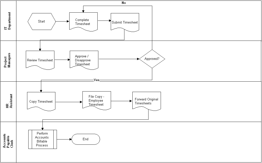
In this article we are going to design part of the Time Management System (TMS). IT Department Staff will use TMS to submit the hours they spend on a customer's project. Project Managers will use TMS to Sign-Off on Timesheets. Human Resources will use TMS to print out a copy of each employee's timesheet for the employee file. The following Business Process Flow Diagram shows the current process used to process timesheets. In the following diagram the timesheets are ultimately sent to the Accounting Department for customer billing, but that aspect of the process is outside the scope of this article.
Features, Use Cases & User Stories
In this section we will take a quick look at the features and use cases we will use to model. We will also translate our use cases into user stories; and, take a look at how we can model user stories.
Feature |
Description |
FE1. Manage Timesheets & Approvals |
This feature manages all requirements associated with creating a timesheet, submitting a timesheet, editing a timesheet, approving a timesheet and disapproving a timesheet. |
Following is a partial list of use cases for TMS. These use cases would be grouped using FE1:
Use Case Name |
Actor |
Flow |
UC1. Submit a Timesheet |
All IT Department Staff |
1. Add a new timesheet. 2. Complete the timesheet. 3. Click the Submit button. The timesheet is submitted. |
UC2. Sign-Off On a Timesheet |
Project Managers |
1. Select a timesheet. 2. Review the timesheet. 3. Click Approve. 4. Submit the timesheet. The timesheet is marked as approved. Alternate Flow: Branch at step 3. 3. Click Disapproved. 4. Submit the timesheet. The timesheet is marked as disapproved. |
UC3. Add a Project |
Project Managers |
1. Select Projects from the menu. The Projects page displays. 2. Click Add Project button. The Add Project page displays. 3. Complete the fields on the page. 4. Click Save. The project is added. |
UC4. Add Project Tasks |
Project Managers |
1. Select Projects from the menu. The Projects page displays. 2. Select a project. The Project Details page displays. 3. Click Add a Project Task. The Add a Project Task Page displays. 4. Complete the fields on the page. 4. Click Save. The project task is added and associated with the selected project. |
UML diagrams provide a way to visually communicate software functionality to developers. An IT professional's design skills should include the ability to translate requirements into a cohesive software design that includes classes, the relationship between classes as well as interaction and communication among objects. As well as the state of an object as events occur.
Use Case Diagram
Use Case Diagrams provide a visual way to depict the use cases that make up a system, the actors that interact with the use cases, and the relationships and type of relationships (i.e., extends, includes) between use cases. Below is a partial TMS Use Case Diagram.
Note that there may be occasion for the stakeholder to agree to reduced functionality to get a part of the system into production as quickly as possible. If this is the case, the two use cases may be assigned different priorities and implemented during separate releases. These releases may or may not be in close proximity to one another.
An extends relationship does exactly what it says. It extends the behavior of a use case such that additional actions can be performed using the extended use case. In the above diagram Sign-off on Timesheet extends Submit Timesheet. This means, the Sign-off on Timesheet inherits most or all of the same capabilities as the Submit Timesheet use case. However, the Sign-off on Timesheet has additional functionality. In this example, the extended behavior is the ability to approve or disapprove a timesheet.
User Story Diagram
User stories can be diagrammed as well. Some developers and project managers may need to see diagrams to reinforce design information. The following diagram shows one way user stories can be captured using the use case diagram concept.
Class Diagram
The Class Diagram shows the classes used to build the application. The class diagram includes the behaviors of the class, shown as operations. For example, the Timesheet class includes the following operations getDate(Today), which is an operation used to return today's date to the timesheet. Each class also includes the attributes of the class. The attributes of the class are implemented as properties of a class. The properties of the class may implement business logic. The operations and the attributes may or may not be implemented in the same class, during development. It all depends on the approach being used to build the software. For example, web services versus regular web classes.
Sequence Diagram
The Sequence Diagram is used to show communication messages between the components or instances of the classes that make up of the application. The TMS Sequence Diagram below shows the communication between the user and the Timesheet, Employee, Projects and Project Task objects.

State Machine Diagram
The State Machine Diagram captures the state of an entity in response to events that affect the entity. The following State Machine Diagram shows the state of the timesheet as events (the text beside the arrows) cause the state (the green rectangles) to change.
Activity Diagram
The Activity Diagram can be used to model the flow within use cases. In the below example, the activity diagram reflects the activity as it pertains to the Timesheet. The forks in the flow capture the alternate flows within the use case. Alternatively, the Activity Diagram can also be used to model user interface screen flows and business process workflows.
Object Oriented Programming (Objects, Events, Methods And Properties)
Understanding Object Oriented Programming concepts is necessary to effective design business applications--particularly complex systems. The following paragraphs provide a brief overview of object oriented programming concepts.
In object oriented programming classes are used to build applications. For example, when you navigate to Facebook and click the Post button, that button was created from a Button class. To create the button object from the button class the developer must create a copy of the button class. The programming language used defines the code that must be written to create the copy. The most important thing about creating a copy of a class is that the copy must be given a unique name. Once a developer creates a copy of the class, also called an object, the developer can customize the object. When the developer creates a copy of the class the developer has actually created an instance of the class.
In .NET all classes are grouped by namespace. Therefore, if the developer wants to find a class he must look under the appropriate namespace. In the following example the the button class is located in the system.web.ui.webcontrols namespace. This makes sense because, in this example, we are building a web application. The buttons and other items on a web page are called controls.
Lets look at what a developer would do to build a web page that a user can interact with. In our example, the developer is going to build the following: 1. a Login page; 2. a field so users can enter a user name; 3. a field for the user's password; 4.a button so users can submit the login credentials; and, 5. a cancel button in case the user changes his/her mind and wants to clear the username and password fields (also called textboxes).
The developer needs to create 5 objects. But, the developer only needs to use 3 classes to create the objects. The developer begins by creating an instance of the Page class and calls it frmLogin. Both the user name and password fields are created from a control called a textbox. Therefore, the Developer creates two instances of the Textbox class. He calls the first Textbox instance txtusername. The second instance is called txtpassword. Lastly the developer needs a submit button and a cancel button. The developer creates 2 instances of the Button class. The first instance of the Button class is called btnSubmit. The second instance of the Button class is called btnCancel. (Note that an IDE does not care what you call an object. You could call an object Goofy or SpongeBob and the IDE would accept those names.)
The developer now has 5 objects. The first is a frmLogin object, which is the login page. The second is called txtusername, which is the object that provides a way for users to enter a user name. The third is called txtpassword, which is the object that provides a way for users to enter a password. The fourth is the btnSubmit button, which is an object that lets users submit the username and password to be validated for accuracy. The fifth is called btnCancel, which is a button object users can click to clear the username and password from the two textboxes.
Properties of a Class
All classes have properties, procedures (including methods) and events, which a Developer can access once an instance of the class is created. In our example, we've already created the instances so we can proceed to set our properties. If we want the Submit button to say "Submit"; and, we want the Cancel button to say "Cancel" we can set the Text property of each button. In VB.NET or C#.NET our code would look something like btnSubmit.Text="Submit" to set the text for the btnSubmit object. Next, we set the Text property of the Cancel button (we called btnCancel). Our code looks similar to btnCancel.Text="Cancel". Doing this causes the user to see two different buttons (a Submit button and a Cancel button) that, from a programming perspective, were developed from the same button class. The following list includes a few of the properties associated with the Button class.
 |
| Properties for the Button Object (or Control) |
Methods & Events
In addition to properties, a class has methods and Events. A method is an existing block of code, also called a procedure, that can be called so an object performs an action. For example, the textbox control has a method called "Clear". When the "Clear" method is called all text is removed from the textbox. In addition to properties and methods, developers can also use an objects Events to add additional behavior to a business application. Each object has a list of events that apply to it. Many events vary from object to object. Also, what happens when the event occurs depends on code written by the developer. For example, a Button object has a Click event. The Click event occurs when the Button object (or control) is clicked. If we want a new page to display when a user clicks a button, we add the applicable code to the button's click event.
Summary
The Unified Modeling Language (UML) is commonly used to model applications, particularly complex business applications. This article discussed the Use Case Diagrams provide a visual way to depict the use cases that make up a system, the actors that interact with the use cases, and the relationships and type of relationships (i.e., extends, includes) between use cases. It also highlighted a way in which user stories can be modeled. This article also discussed the class diagram, which includes the behaviors of the class and the behaviors referred to as operations. And it discussed the the State Machine Diagram, which captures the state of an entity in response to events that affect the entity. Lastly, it provided an overview of the Activity Diagram, which can be used to model the flow within use cases as well as user interface screen flows and business process workflows.
If you are interested in learning more about programming following is a list of books you may consider purchasing. Once you get the books, you can download the code samples at: www.murach.com/downloads/index.htm.
1. Murach's Java Programming
2. Murach's ASP.NET 4 Web Programming with C# 2010
3. Murach's JavaScript and DOM Scripting
4. Murach's HTML5 and CSS3